I wanted to see how much of a functional brushless motor I could build from scratch using mostly 3D-printed parts and basic off-the-shelf components. The target was simple: magnets, bearings, shaft, copper wire, and a motor driver making a real rotor spin.
Project Photo
First Prototype Scope
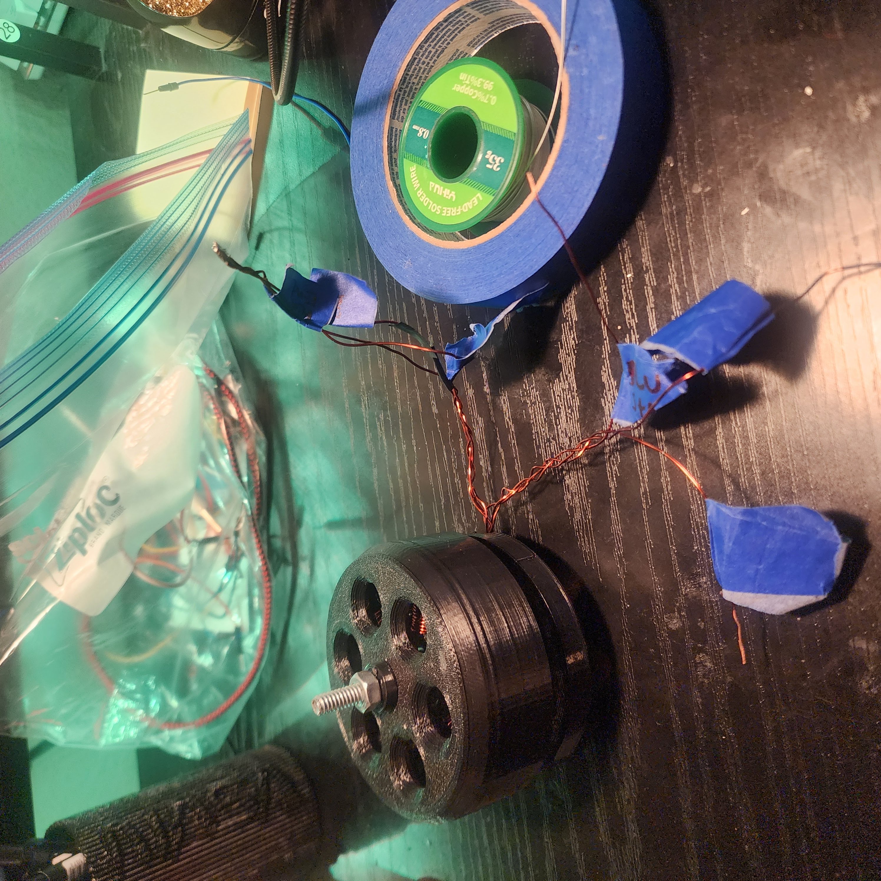
This first version was a proof of concept printed on an Ender 3. The printer's wider tolerances made precise coil spacing and rotor balance difficult, which hurt magnetic coupling and overall efficiency from the start.
Configuration and Components
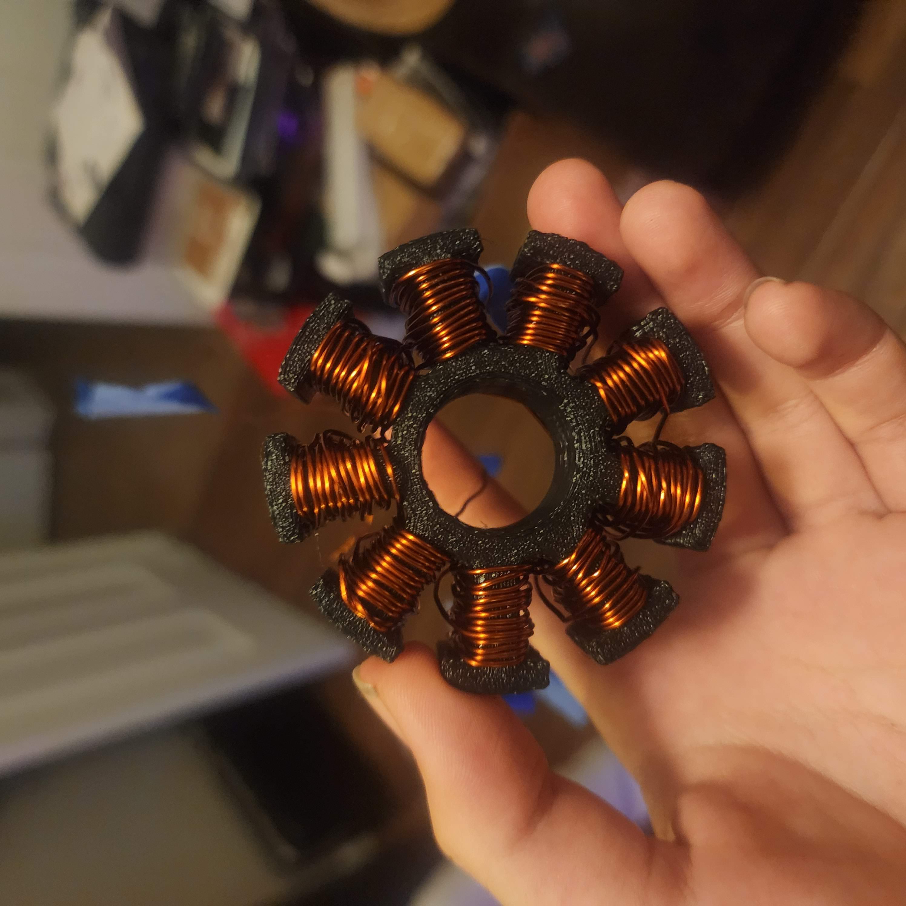
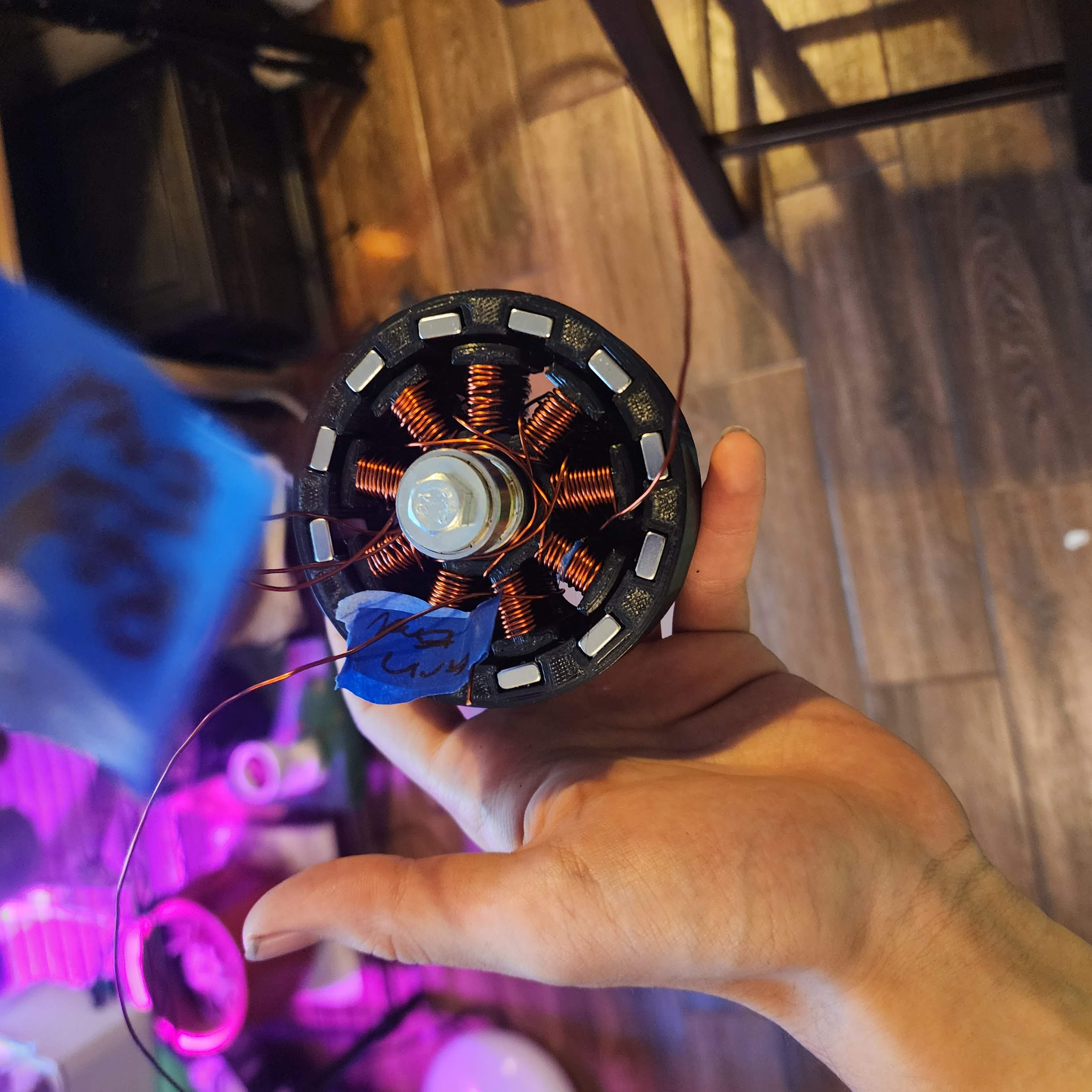
I used an outrunner-style architecture with 24 AWG coil windings, standard bar magnets, and skateboard bearings. The outrunner layout made hand-wrapping coils and balancing the rotor more approachable than an inrunner setup.
Winding Pattern
The stator followed a 9N12P pattern similar to old CD-ROM motor topology. It gave good spacing for this geometry, but limited turns per tooth, which constrained available torque.
Primary Mechanical Challenge
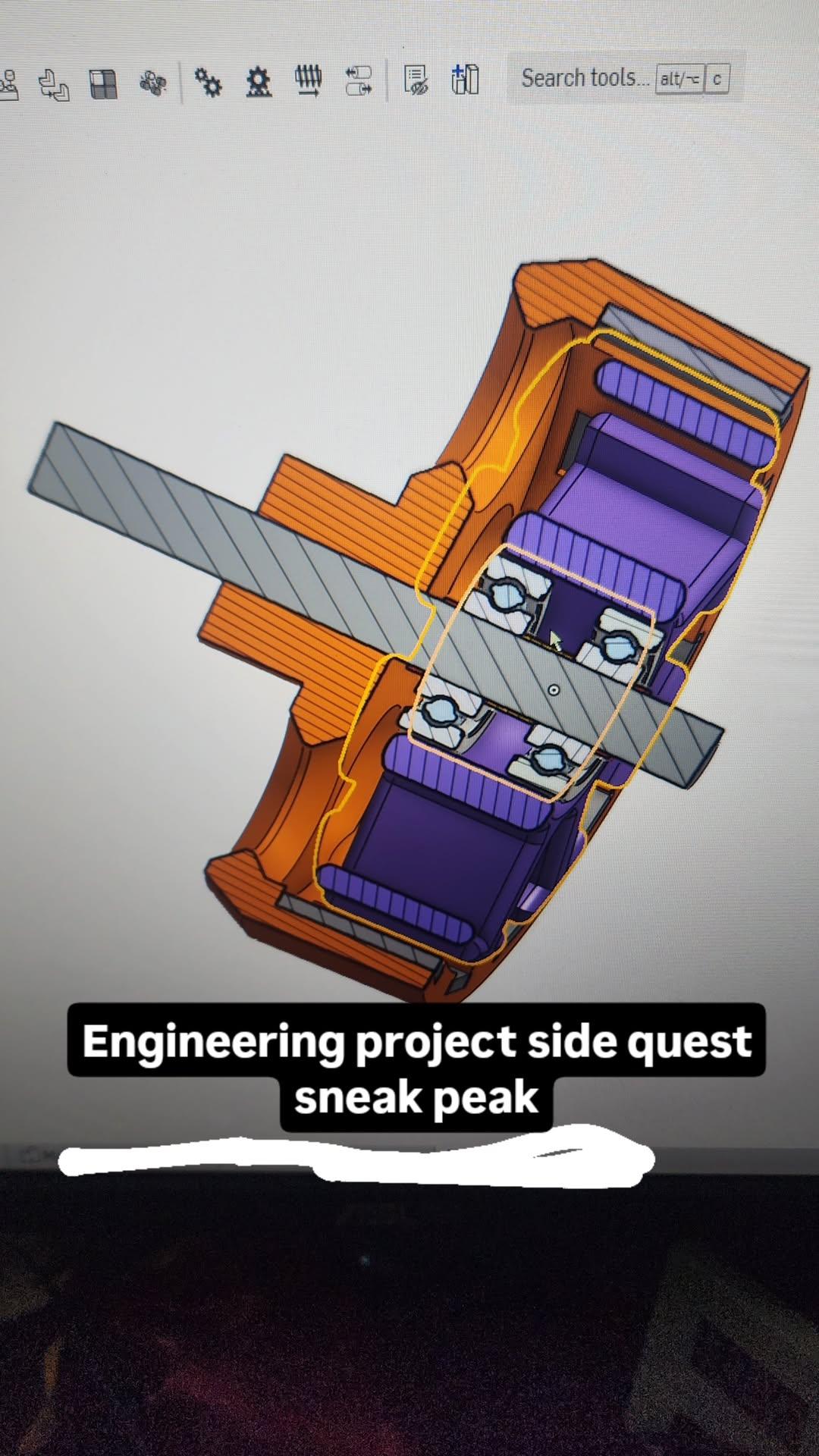
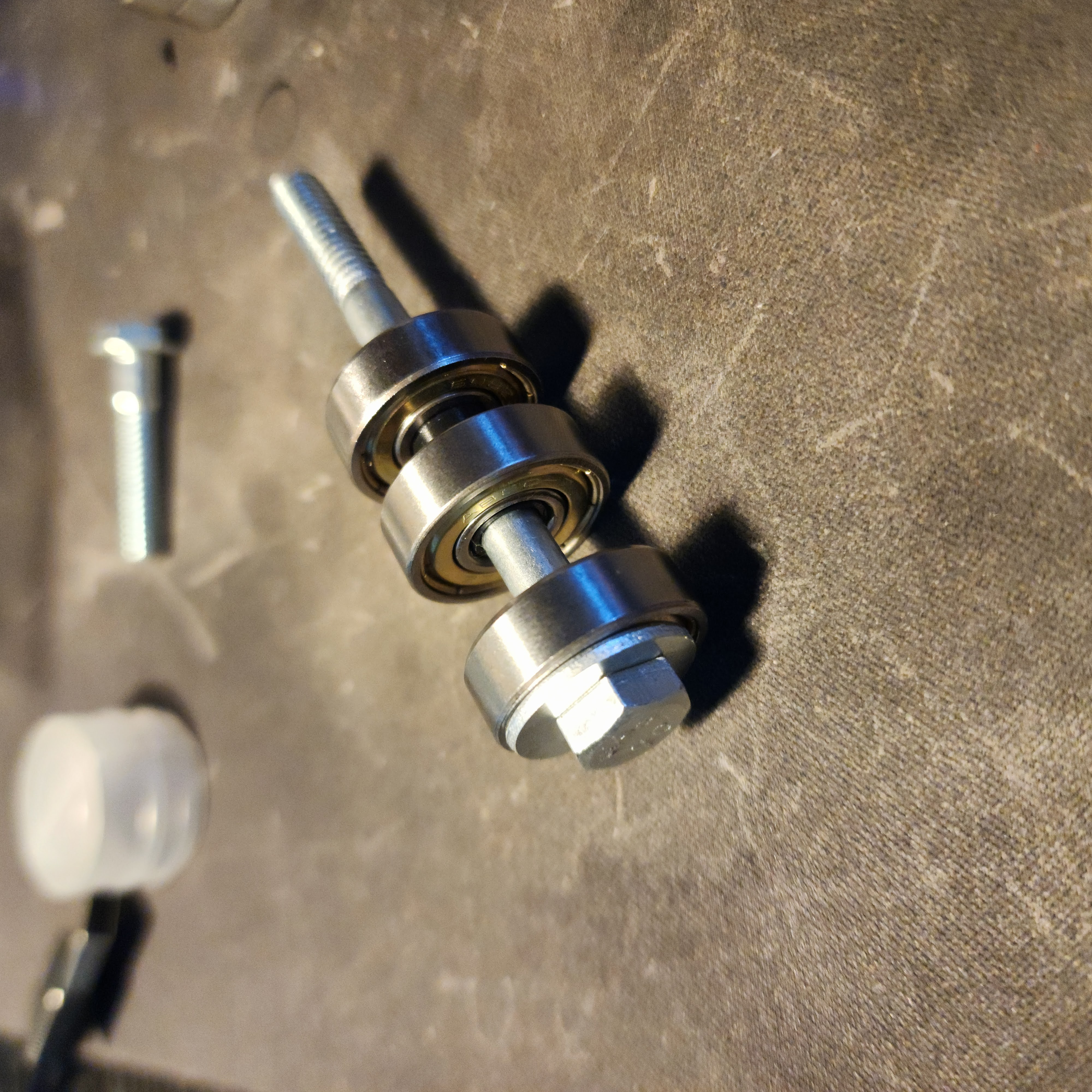
The hardest part was securing shaft and rotor while keeping friction low. I clamped the bearing inner faces against the rotor structure with a bolt acting as the shaft. It worked, but introduced axial loading that increased friction, generated heat, and cut performance.
Results and Lessons Learned
Even with those issues, the motor reached roughly 100 RPM on 12 V. It was weak, but seeing it self-start and run validated the concept. This project taught me how tightly mechanical precision, friction management, and electromagnetic design are coupled, and why iteration is everything in motor development.
More Photos